This helping system in the installation allows the installer to identify in each cascade multiswitch all the cables
that are in the input. It provides the correct position of the cable that we want to connect at any time, by the
means of the display of the multiswtich. In order to make a correct use of this system you must follow the
following steps:
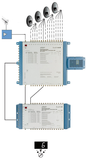
1.- Verify the status of the power supply’s led of the headend cascade multiswitch. If the light of the LED is
fix, the device is running correctly, if on the contrary it is flicking or the LED is off, it indicates that there is a
short-circuit or that the feeding of the device is overloaded.
2.- Connect it to the headend cascade multiswitch output.
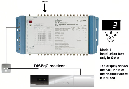
3.- Turn the small switch of the indicator of position to the position “Mode 2”.
4.- Try to connect the main cables that come from the headend one by one tothe multiswitch terrestrial signal
input. The moment when a “0” appears in the display, it will show the terrestrial signal cable.
5.- Once the terrestrial signal cable is correctly connected, we have to select another downlink and connect
it in the first multiswitch satellite input. The display will show which the correct input of the cable is.
6.- Repeating the last instruction until we have all the satellite signal cable connected. If during the process of
installation, when connecting a cable the position of the display got erased, keep this cable aside and connect
it once the remaining cables are fixed in their correct position.
7.- The process for installing the resting multiswitches of the installation is the same.
8.- In the case where we have to install a cascade line amplifier, it has to be placed just before the input or just
after the output, depending on the function (pre or post amplifier). Each single path of the amplifier allows the
direct current to go through, from the input to the output.
9.- The small connection cables between the amplifier and the multiswitch can not be crossed.
10.- If the display shows a mark after having fixed it correctly, it is possible that one of the cables has a
short-circuit.
11.- In the last cascade multiswitch, the main outputs have to be ended with charges of 75 Ohms. If at the
moment when the endings are connected a “0” appears, it will be necessary to check this output because it is
possible that it has a short-circuit.
12.- After completing the installation, we must fix all the switches of the multiswitch in the “Off” position.
|